Key Takeaways
- Trapped air causes spongy controls, jerky movements, cavitation damage, and reduced efficiency
- Position system at correct angle and cycle controls slowly while monitoring fluid levels
- Repeat bleeding cycles until all movements are smooth and responsive
- Closed-loop systems require more attention than open-loop due to direct pump recirculation
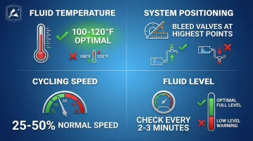
- Maintaining 100-120°F fluid temperature and proper bleed point positioning ensures successful air removal
- Prevention through proper maintenance and quality components reduces bleeding frequency and extends system life
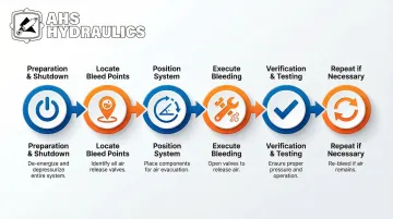
How to Bleed Air from Closed Loop Hydraulic Systems
Step 1: Preparation and System Shutdown
Park equipment on level ground, engage parking brakes, lower all implements to the ground, and allow the system to cool to safe working temperature (below 140°F). Hot fluid causes burns and makes handling components dangerous.
Safety checks:
- Wear chemical-resistant gloves and safety glasses
- Ensure adequate ventilation, especially when working indoors
- Have absorbent materials (pads or rags) ready for spills
- Place drip pans under potential leak points
Tools:
- Correctly sized wrenches for bleed valves (typically 1/2" to 3/4")
- Clean containers for catching fluid (minimum 1-gallon capacity)
- Hydraulic fluid matching manufacturer specifications (at least 2 gallons reserve)
- Clean, lint-free rags
- Pressure gauges if not built into the system
Step 2: Locate and Prepare Bleed Points
Bleed valves in closed-loop systems sit at high points in the circuit—on top of cylinders, at elevated points on manifolds, or at the highest point of hydraulic lines.
Unlike open-loop systems where air naturally escapes through the vented reservoir, closed-loop designs require intentional air removal through these specific points.
Check your operator's manual for system-specific bleed point locations and the recommended bleeding sequence.
Different equipment manufacturers place bleed valves in different locations, and following the wrong sequence traps air in sections you've already bled.
Once you've identified the bleed points, clean the area thoroughly using a clean rag and, if necessary, a mild solvent.
This prevents dirt, debris, or old fluid from entering the system when you open valves. Even small particles damage precision components and cause system failure.
Step 3: Position System for Optimal Air Removal
Position cylinders and actuators to place bleed valves at the highest point possible. Air naturally rises, so proper positioning allows bubbles to migrate toward exit points rather than becoming trapped in low spots.
Orient hoses and components to create a continuous upward path for trapped air:
- Extend cylinders fully to elevate bleed points
- Position actuators at specific angles to create upward paths
- Eliminate "pockets" where air collects in low spots
Closed-loop systems may require cycling actuators through their full range of motion multiple times to move air toward bleed points. The recirculating design means air travels in circular patterns, so strategic actuator positioning helps break the circulation and guide air toward exits.
Step 4: Execute the Bleeding Procedure
Opening sequence:
- Start with the bleed point furthest from the pump
- Slowly open the bleed valve counterclockwise (typically 1/4 to 1/2 turn)
- Watch for fluid flow—initial discharge will likely be foamy or contain visible bubbles
Cycling process:
- Slowly operate controls through their full range of motion 5-10 times while the bleed valve remains open
- Operate at 25-50% of normal speed to prevent turbulence from breaking large air pockets into smaller bubbles
- Watch the fluid transition from foamy/bubbly to clear and consistent
Critical maintenance: Continuously monitor reservoir fluid level during bleeding. Add manufacturer-specified fluid as needed—never let the level drop below the minimum mark. Low fluid levels can introduce new air even while you're trying to remove existing air, creating a frustrating cycle.
Closing procedure: Close bleed valves clockwise only after observing steady, bubble-free fluid flow for at least 30 seconds. Tighten to manufacturer specifications—overtightening damages valve seats, while undertightening allows leaks.
Step 5: Verification and System Testing
Operate each hydraulic function under no-load conditions first. Feel for smooth, consistent response without spongy or jerky movement. Spongy controls indicate remaining air; jerky motion suggests air pockets moving through the system.
Listen carefully for unusual noises:
- Knocking or banging indicates aeration (air entering from outside)
- Whining or sounds like marbles suggests cavitation (vapor bubbles forming)
- Hissing may indicate leaks allowing air entry
Final checks:
- Inspect all bleed points for leaks, tightening if necessary
- Verify proper fluid level in the reservoir
- Test under normal operating load, monitoring for any performance issues
Test under normal operating load, monitoring for any performance issues. If you're working with Timberwolf firewood processing equipment or similar heavy machinery, HydraWolf Hydraulics manufactures replacement hydraulic components including cylinders, valves, and fittings designed for these demanding applications
Step 6: Repeat if Necessary
Closed-loop systems often require multiple bleeding cycles, especially after major repairs or if the system was completely drained.
The recirculating design traps air more stubbornly than open-loop systems, where air naturally vents through the reservoir.
Repeat the process if:
- Spongy feel persists after initial bleeding
- Unusual noises continue during operation
- Actuators move erratically or lack full power
- Foam appears in the reservoir or sight glass
Allow 15-30 minutes between bleeding cycles for the system to stabilize and remaining air to migrate toward bleed points.
When Should You Bleed Air from Closed Loop Hydraulic Systems?
Bleeding isn't routine maintenance. It becomes necessary when your hydraulic system has been opened or exposed to air.
Typical scenarios requiring bleeding:
- After hydraulic component replacement (pumps, motors, valves, cylinders)
- Following fluid changes or system flushes
- When fluid level dropped low enough to expose suction lines to air
- After system repairs that required opening hydraulic lines
- When performance symptoms indicate air presence (spongy controls, erratic movement, unusual noises)
Bleeding removes trapped air, but it won't fix underlying problems. Address these issues first:
When bleeding alone won't solve the problem:
- Active leaks continuously allowing air entry—repair leaks first
- Damaged seals requiring replacement before bleeding
- Contaminated fluid needing complete system flush
- Worn pump components internally aerating fluid
Industry data shows that 80-90% of hydraulic system failures stem from fluid contamination, including air and water. Before bleeding, identify and fix what's letting air into your system.
What You Need Before Bleeding Air from Your Hydraulic System
Proper preparation and having the right materials directly affects bleeding effectiveness and prevents introducing new problems during the process.
Equipment and Tool Requirements
Minimum required tools:
- Wrenches sized for your bleed valves (check manual)
- Clean catch containers (minimum 1-gallon, preferably clear)
- Pressure gauge if not built into system
- Manufacturer-specified hydraulic fluid (minimum 2-gallon reserve)
A reliable pressure gauge helps you monitor system pressure throughout the bleeding process, ensuring you maintain proper charge pressure levels.
Safety and Environmental Readiness
Safety equipment needed:
- Chemical-resistant gloves (hydraulic fluid degrades latex)
- Safety glasses or face shield (pressurized fluid can spray)
- Protective clothing (long sleeves, closed-toe shoes)
- Spill containment materials (absorbent pads, drip pans)
Environmental considerations:
- Proper disposal containers for used hydraulic fluid (check local regulations)
- Awareness of environmental regulations regarding hydraulic fluid disposal
- Adequate ventilation if working indoors (hydraulic fluid vapors can accumulate)
System-Specific Information
Keep your equipment operator's manual or hydraulic system schematic readily available. These documents show bleed point locations, recommended bleeding sequence, fluid specifications, and torque values for bleed valves.
Without this information, you risk missing critical bleed points or using incorrect procedures that leave air trapped in the system.
Key Parameters That Affect Bleeding Results in Closed Loop Systems
Bleeding success depends on controlling several variables that affect how air moves through and exits the system.
Fluid Temperature
Warm fluid makes bleeding significantly easier. At 100-120°F, hydraulic fluid has lower viscosity, allowing air bubbles to separate and rise naturally.
Cold fluid resists bubble movement due to higher viscosity, trapping air in the system.
OEMs like Danfoss recommend maintaining fluid temperature in the 100-120°F range during bleeding procedures. Systems bled with cold fluid often require repeated bleeding cycles once the system reaches operating temperature and the fluid thins, releasing previously trapped air.
System Positioning and Orientation
Air naturally rises to high points in the system. Position bleed valves at the highest elevation in each circuit section for effective air removal.
Closed-loop systems present a unique challenge: fluid recirculation moves air bubbles in circular patterns rather than straight to exit points. Strategic actuator positioning breaks this circulation and guides air toward bleed valves.
For example, fully extending a cylinder may position the bleed valve at the highest point, while a partially extended position might trap air in the cylinder barrel.
Cycling Speed and Pressure
Controlled cycling speed makes a measurable difference in bleeding effectiveness. Fast movements can break large air pockets into smaller bubbles that become harder to purge, while slow cycling allows air to combine into larger bubbles that escape more readily.
Recommended cycling approach:
- Operate at 25-50% of normal speed during bleeding
- Allow air time to separate from fluid and migrate to bleed points
- Avoid rapid movements that churn air throughout the system
Fluid Level Maintenance
Reservoir level drops quickly during bleeding in closed-loop systems. Low fluid levels introduce new air even while you're removing existing air, creating a counterproductive cycle.
Fluid maintenance checklist:
- Check reservoir level every 2-3 minutes during active bleeding
- Top off immediately when level drops
- Use only manufacturer-specified fluid
- Never mix different fluid types or viscosities (causes compatibility issues and degrades performance)
Common Mistakes When Bleeding Air from Closed Loop Hydraulic Systems
Several common errors make bleeding more difficult or introduce new problems:
Rushing the process — Cycling controls too quickly or not allowing adequate time for air to move to bleed points results in incomplete removal. Proper bleeding takes 30-45 minutes for most systems, and rushing saves no time if you must repeat the entire process.
Failing to maintain proper fluid level — Adding new air while trying to remove existing air creates a frustrating cycle where you never fully purge the system. If working with a team, assign one person to monitor fluid level continuously during bleeding.
Ignoring the correct bleeding sequence — Working from furthest point to closest point from the pump prevents trapping air in sections already bled. Air moves toward the pump during operation, so bleeding from furthest to nearest ensures you don't push air back into cleaned sections.
Operating at full speed — High-speed operation creates turbulence that fragments air pockets into fine bubbles dispersed throughout the fluid. According to Fluid Power Journal, these micro-bubbles are much harder to remove than larger pockets that rise naturally to bleed points.
Troubleshooting Issues While Bleeding Air from Your System
Bleeding doesn't always go smoothly. Persistent problems require systematic diagnosis to identify root causes.
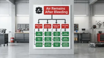
Air Remains After Multiple Bleeding Cycles
Common causes include active leaks in the suction side, worn pump seals internally aerating fluid, incorrect bleeding sequences, or bleed points not positioned at true high points.
To diagnose and resolve:
- Check all suction-side connections for tightness using a torque wrench
- Inspect pump for unusual noise or vibration indicating internal wear
- Review system schematic to identify any overlooked bleed points
- Consider using ultrasonic leak detection to locate hard-to-find air entry points
Fluid Becomes Milky or Foamy During Bleeding
If fluid appears milky during bleeding, you're likely cycling too fast, working with cold fluid, or dealing with water contamination.
Try these solutions:
- Slow cycling speed to 25% of normal speed maximum
- Warm system to operating temperature before bleeding
- Test fluid for water contamination if milky appearance persists
- Place a fluid sample in a clear container—if it clears as bubbles rise, it's air; if it stays cloudy, suspect water mixing with the fluid
System Pressure Won't Build After Bleeding
When pressure won't build after bleeding, check for bleed valves left partially open, internal pump damage from cavitation, incorrect fluid viscosity, or relief valves stuck open.
Key troubleshooting steps:
- Verify all bleed valves are fully closed and tightened to specification
- Check pump function under no-load conditions, listening for unusual noise
- Confirm fluid specifications match manufacturer requirements (using ISO 32 fluid in a system designed for ISO 46 can prevent proper pressure buildup)
Spongy Feel Returns Shortly After Bleeding
If sponginess returns after successful bleeding, air is re-entering the system through leaks in the suction line, dropping fluid levels, dissolved air coming out of solution as fluid heats, or worn pump shaft seals.
Steps to identify the source:
- Pressure test suction lines to locate leaks
- Verify reservoir capacity is adequate—undersized reservoirs can't maintain proper levels during high-demand operations
- Inspect pump shaft seals for wear or damage
- Consider fluid deaeration if problem persists with no leaks found
Using quality components like properly sized hydraulic cylinders, reliable fittings, and effective filtration reduces the likelihood of air entry and simplifies bleeding when maintenance is required.
Alternatives to Manual Bleeding of Hydraulic Systems
Manual bleeding works well for routine maintenance, but three situations call for alternative approaches: systems with multiple circuits, deeply trapped air in complex manifolds, or frequent maintenance cycles where downtime costs add up quickly.
Vacuum Bleeding Systems
Vacuum bleeding applies negative pressure to bleed ports to actively pull air out rather than relying on system pressure to push air out. This approach is particularly effective for systems with difficult-to-access bleed points or when air is deeply trapped in complex manifolds.
This method excels in four scenarios:
- Systems with multiple circuits and numerous bleed points
- Air deeply trapped in complex manifolds or valve bodies
- Large systems where manual bleeding is too time-consuming
- Critical applications requiring thorough air removal
Vacuum bleeding systems can achieve >99% air removal in a single cycle. They require specialized vacuum equipment and fittings, which increases initial cost. However, labor time drops significantly—from 30-45 minutes for manual bleeding to under 15 minutes with vacuum systems.
Self-Bleeding System Design
Some modern hydraulic systems incorporate automatic air purging features such as continuously vented reservoirs, strategically placed automatic bleeder valves, or fluid circulation paths designed to naturally separate and evacuate air.
These systems make sense for critical applications where air contamination cannot be tolerated, operations with frequent maintenance requiring line opening, or equipment where manual bleeding access is impractical. High-value equipment where downtime costs justify higher initial investment also benefits from this approach.
The trade-off is higher initial system cost and complexity. However, maintenance time drops dramatically and air removal becomes more reliable.
Automatic bleed valves can reduce bleed time from 30-45 minutes to under 12 seconds for valve closure, providing consistent startup protection without manual intervention.
Professional Hydraulic Service
Professional service is the better choice for complex closed-loop systems with multiple circuits, when specialized diagnostic equipment is needed to locate air entry points, or when persistent air problems suggest underlying component failure.
Professional service provides several key advantages:
- Access to specialized tools (vacuum bleeders, ultrasonic leak detectors, fluid analysis equipment)
- Expertise in system-specific bleeding procedures
- Ability to diagnose and repair root causes of air entry (worn seals, damaged components, design flaws)
- Warranty protection if repairs are needed
The immediate cost is higher compared to DIY bleeding. However, it prevents repeated attempts and potential damage from operating air-contaminated systems.
Research shows that just 2% air entrainment can reduce pump performance by 12%, while 4% air drops performance by 40%. Professional service prevents this costly performance degradation.
Conclusion
Bleeding air from closed-loop hydraulic systems requires patience, proper technique, and attention to key variables like fluid temperature (100-120°F optimal), system positioning, and controlled cycling speed.
Most bleeding problems stem from rushing the process, failing to maintain fluid levels during bleeding, or not addressing the root cause of air entry.
Combining proper bleeding technique with preventive maintenance—including regular inspection of suction-side connections, maintaining proper fluid levels, and using quality filtration—reduces bleeding frequency and extends system life.
Starting with quality components makes a difference. HydraWolf Hydraulics manufactures hydraulic cylinders, fittings, and breather filters designed to minimize air entry points and simplify maintenance when bleeding becomes necessary.
Frequently Asked Questions
What will happen if there is air trapped in the hydraulic system?
Trapped air causes spongy controls, erratic actuator movements, and increased heat generation. The cavitation from imploding air bubbles can erode pump surfaces, damage valve seats, and degrade seals over time.
Where is the bleeder valve on a hydraulic system?
Bleed valves are located at high points in the hydraulic circuit—on top of cylinders, elevated manifold points, or at the highest point of hydraulic lines. Consult your operator's manual for exact bleed point locations in your system.
How long does it take to bleed air from a closed-loop hydraulic system?
Bleeding takes 15-45 minutes depending on system size and air quantity. Closed-loop systems require more time than open-loop systems due to their recirculating design. Rushing leads to incomplete removal and wasted effort.
Can air in hydraulic systems cause permanent damage?
While air itself doesn't directly damage components, the cavitation it causes can erode pump surfaces, damage valve seats, and degrade seals over time. Prompt air removal is important to prevent these costly repairs and maintain system reliability.
How do you prevent air from entering a closed-loop hydraulic system?
Maintain proper fluid levels, repair leaks promptly (especially suction-side), follow proper service procedures when opening lines, and torque all connections to specification. Quality breather filters from HydraWolf Hydraulics prevent contamination while allowing proper venting.
What's the difference between bleeding open-loop and closed-loop hydraulic systems?
Open-loop systems return fluid to a vented reservoir where air naturally escapes, making bleeding simpler and often self-correcting. Closed-loop systems recirculate fluid directly to the pump, trapping air more stubbornly and requiring deliberate bleeding with attention to bleed points and cycling techniques.