Introduction
Shaft couplings are essential mechanical components that connect rotating shafts in industrial machinery to transmit power while accommodating misalignment. These connectors are critical in industrial operations—they protect equipment from damage, reduce downtime, and extend machinery lifespan.
Bearing failures account for 40-70% of rotating machinery malfunctions, with shaft misalignment identified as a critical root cause. This makes proper coupling selection essential for applications ranging from pumps and compressors to heavy manufacturing equipment.
This guide explains what shaft couplings are, explores the main types available, details their specific applications and advantages, and provides practical guidance on selecting the right coupling for different industrial needs.
Key Takeaways
- Couplings transmit power between shafts while protecting equipment from misalignment damage
- Rigid couplings require precise alignment; flexible couplings accommodate misalignment and dampen vibration
- Match coupling type to your torque load, speed, and misalignment tolerance to prevent premature failure
- Correct coupling selection cuts downtime and extends component life
What Are Shaft Couplings?
Equipment operators know the frustration: misaligned shafts cause premature bearing failure, excessive vibration, and costly downtime. Shaft couplings solve this problem by connecting driving and driven shafts while compensating for angular, parallel, and axial misalignment during power transmission.
These mechanical connectors transmit rotational power and torque across:
- Motors, pumps, and compressors
- Conveyors and material handling systems
- Generators and manufacturing equipment
- Hydraulic power units and drive assemblies
Beyond simple connection, couplings protect your equipment. They absorb vibration, accommodate thermal expansion, and prevent damage from operational shifts—extending component life and reducing maintenance costs.
Why Shaft Couplings Are Critical in Industrial Applications
In hydraulic systems and power transmission applications, shaft couplings serve as the critical link between rotating components. When selected correctly, they prevent bearing failure, reduce maintenance costs, and extend equipment life across demanding industrial operations.
Without proper coupling selection, problems develop quickly:
- Excessive vibration leads to premature bearing wear
- Misalignment causes shaft damage and geometric stress concentration spalling on bearing rings
- Shock loads destroy connected components
- Rigid connections fail when flexibility is needed
The right coupling choice directly affects total cost of ownership. Initial investment in quality couplings pays dividends through reduced maintenance, longer equipment life, and fewer catastrophic failures.
Consider this: only 0.5% of bearings fail from actual damage. The other 99.5% are replaced preventively, demonstrating how proper coupling selection prevents problems before they start.
Types of Shaft Couplings
Shaft couplings fall into two primary categories: rigid and flexible. Rigid couplings provide a solid connection between perfectly aligned shafts, while flexible couplings accommodate misalignment and absorb shock loads during operation.
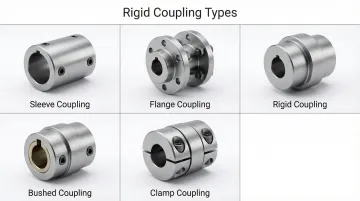
Rigid Couplings
Rigid couplings create a permanent, inflexible connection between two shafts. These couplings work best when shafts are precisely aligned and the application doesn't involve shock loads or vibration.
Common rigid coupling types include:
- Sleeve (Muff) Couplings: Simple cylindrical sleeves that fit over shaft ends, secured with keys or set screws
- Flange Couplings: Two flanges bolted together, providing high torque capacity for heavy-duty applications
- Clamp (Compression) Couplings: Split sleeves that compress around shaft ends, allowing easy installation without moving connected equipment
Rigid couplings are ideal for applications like conveyor systems, pumps with precisely aligned motors, and situations where shaft alignment remains constant.
Flexible Couplings
Flexible couplings compensate for misalignment while transmitting torque between shafts. They absorb vibration, reduce shock loads, and protect connected equipment from damaging forces.
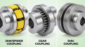
Key flexible coupling types include:
- Jaw Couplings: Elastomer spider between two hubs provides flexibility and electrical insulation
- Gear Couplings: Toothed hubs mesh together, handling high torque with angular misalignment compensation
- Disc Couplings: Thin metal discs flex to accommodate misalignment while maintaining torsional rigidity
- Elastomeric Couplings: Rubber or urethane elements absorb shock and dampen vibration
- Oldham Couplings: Three-piece design handles parallel misalignment in servo and encoder applications
Flexible couplings are essential for hydraulic pump drives, agricultural equipment, construction machinery, and any application where perfect alignment is difficult to maintain.

Selection Factors
Choose the right coupling based on these operational factors:
- Misalignment tolerance: Angular, parallel, or axial shaft offset that must be accommodated
- Torque capacity: Maximum transmitted power and peak load conditions
- Operating speed: RPM range and potential for critical speed resonance
- Environmental conditions: Temperature extremes, chemical exposure, moisture, or contaminants
- Space constraints: Radial and axial dimensions available for coupling installation
- Maintenance access: Frequency of inspection requirements and ease of replacement
For hydraulic systems in firewood processors, log splitters, and heavy machinery, flexible couplings typically provide the best balance of misalignment tolerance and shock absorption needed for reliable operation.
Rigid Couplings
Rigid couplings create zero-flexibility connections requiring precise shaft alignment. They're ideal for applications with permanently aligned shafts or where maintaining exact positioning is critical.
Primary use cases include vertical pump applications, precision machinery, and situations where shaft alignment can be maintained throughout operation.
Once connected, rigid couplings prevent any relative motion. Any axial or radial misalignment results in high stress and potential failure.
Sleeve (Muff) Coupling
Sleeve coupling is the simplest rigid coupling design: a hollow cylindrical sleeve that fits over both shaft ends. Keys and set screws secure the connection.
Power transmits through the sleeve and key, with the cylindrical design providing a straightforward mechanical connection. This simplicity makes it the slimmest coupling design available.
Works best for light to medium-duty torque transmission where shafts are perfectly aligned and cost-effectiveness matters.
Key advantages:
- Simple design requiring minimal components
- Easy to manufacture and install
- Economical for appropriate applications
- Compact profile for space-constrained installations
Flange Coupling
For heavier-duty applications, flange couplings offer a more robust solution. These use two flanges—one per shaft—bolted together face-to-face, with alignment maintained through projecting rings and recesses.
Three main types exist:
- Unprotected: Exposed bolts for easy access
- Protected: Enclosed bolts for safety in hazardous environments
- Marine: Tapered bolts for superior vibration resistance
Common in heavy-duty power transmission, pressurized piping systems, large shaft diameters, and applications requiring high torque capacity.
Strengths:
- Excellent for high torque transmission
- Creates effective seals in fluid systems
- Durable for demanding conditions
- Provides secure positive connection
Flexible Couplings
Flexible couplings accommodate misalignment—angular, parallel, and axial—while transmitting torque, making them suitable for most real-world industrial applications where perfect alignment is impossible to maintain.
They protect equipment by absorbing shock loads, dampening vibrations, compensating for thermal expansion, and reducing stress on bearings and connected components.
Jaw (Spider) Coupling
These material-flexing couplings feature two hubs with interlocking jaws separated by an elastomeric spider element that transmits torque through compression.
The flexible spider deforms to allow angular and parallel offset while maintaining torque transmission. Available in 24 sizes with bore ranges from 0.125 to 7 inches, jaw couplings deliver torque capacity from 3.5 to 170,000 in-lbs.
Best-suited applications: General industrial equipment, motion control systems, pumps, conveyors, and applications requiring vibration dampening with zero backlash.
Key benefits:
- No lubrication required
- Excellent vibration isolation
- Fail-safe design—spider fails before equipment damage
- Easy maintenance with simple element replacement
- Resistant to oil and moisture
Jaw couplings deliver reliable performance in firewood processing equipment and heavy machinery, handling demanding outdoor environments with exposure to vibration and shock loads.
Gear Coupling
High-capacity gear couplings use crowned external gear teeth on hubs that mesh with internal gear teeth on sleeves. This design transmits very high torque.
Gear tooth engagement allows angular misalignment (1.5° per mesh standard, up to 6° for special designs) while the crowned tooth profile maintains contact through shaft movement. This design delivers exceptional power density and bore-limited torque capacity.
Ideal applications: Heavy industrial machinery, high-torque high-speed applications, turbines, large compressors, and metal processing equipment.
Advantages and trade-offs: Exceptional torque capacity and high-speed capability make gear couplings ideal for demanding applications. However, they require regular lubrication—lack of proper lubricant is the principal cause of failure. While Long Term Grease (LTG) can extend relubrication intervals to three years, general-purpose greases require bi-annual checks to prevent scuffing and tooth wear. They also have higher backlash than some alternatives.
Grid Coupling
A serpentine spring steel grid meshes with slots in two hubs, transmitting torque while flexing to handle misalignment.
The spring steel grid (shot-peened high-tensile alloy) absorbs shock loads and dampens torsional vibrations by flexing between hub teeth during misalignment and load variation. This design provides a high torque-to-outer-diameter ratio.
Best applications: Reciprocating equipment, applications with shock loads, moderate to high torque transmission, and situations requiring vibration dampening.
Key strengths:
- Excellent shock absorption protecting connected equipment
- Effective vibration dampening
- High torque density in compact package
- Protects equipment from load spikes
- LTG grease extends relubrication intervals to 5+ years
Disc Coupling
High-performance disc couplings use thin metallic disc packs bolted between hubs. Torque transfers through tangential bolt loading.
The thin discs flex between bolts to handle misalignment (0.5° to 1.5° angular per disc pack) while maintaining torsional rigidity for accurate power transmission.
Stainless steel disc packs (AISI-301) offer high resistance to environmental conditions.
Ideal applications: High-speed turbomachinery, precision equipment, applications requiring low maintenance, and systems where lubrication-free operation is essential. API 610 and API 671 compliant designs suit critical petroleum and chemical applications.
Advantages:
- No lubrication required
- High torsional stiffness with zero backlash
- Excellent misalignment capability
- Minimal maintenance requirements
- Infinite life when operated within design limits
- Inherently balanced for high-speed applications
Critical note: "Infinite life" is conditional—it depends on operating within specific fatigue limits. Overloads or excessive misalignment can lead to rapid fatigue failure, such as cracks near bolt holes.
Oldham Coupling
This specialized coupling uses three discs—two hubs with perpendicular slots and a center disc with perpendicular tongues—designed specifically for parallel shaft offset.
The center disc (typically acetal, nylon, or PEEK) slides in perpendicular grooves to handle lateral misalignment while rotating. This makes it ideal for shafts at different elevations.
It can handle parallel misalignment up to 10% of its outer diameter.
Best applications: Applications with significant parallel misalignment, compact installations requiring zero backlash, and motion control systems.
Key benefits:
- Handles substantial parallel offset
- Compact design
- Zero backlash capability
- Electrically isolating
- Constant velocity transmission
Beam (Helical) Coupling
Machined from a single piece of material, these precision couplings feature helical cuts creating a curved flexible beam that handles misalignment.
Available in aluminum or stainless steel, the helical cut pattern provides flexibility for angular, parallel, and axial misalignment without compromising structural integrity.
Ideal applications: Servo motors, motion control, robotics, encoders, and low-power precision positioning systems.
Advantages:
- Zero backlash from one-piece design
- Excellent response characteristics
- No maintenance required
- Can be customized for specific misalignment needs
- Constant velocity transmission
- High torsional stiffness
Diaphragm Coupling
Thin flexible metal diaphragms (membranes) transmit torque in these high-performance couplings while handling multiple misalignment types.
One or more flexible diaphragms connect drive flanges to an intermediate member, flexing to allow misalignment.
Advanced designs use single stainless steel diaphragms with variable thickness profiles to distribute stress evenly.
Best applications: Turbomachinery, high-speed compressors, generators, and applications requiring high torque at high speeds without lubrication. API 671 and ISO 10441 compliant for critical applications.
Key strengths:
- No lubrication needed
- Accommodates all misalignment types
- High-speed capability
- Excellent for demanding industrial environments
- Field replaceable elements
- Maintenance-free operation
Tire (Tyre) Coupling
A thick rubber, polyurethane, or polyether element connects two hubs in tire couplings, transmitting torque through shear forces.
The elastic element absorbs shock and accommodates significant misalignment (up to 4° angular) while dampening vibrations effectively. Split-in-half element designs allow replacement without moving hubs or equipment.
Best applications: Moderate to high torque at moderate speeds (up to 4,200 RPM), equipment with vibration issues, and general industrial machinery.
Advantages:
- Excellent shock and vibration absorption
- Handles high misalignment
- Simple maintenance with split element design
- Cost-effective for many applications
- No lubrication required
Fluid (Hydraulic) Coupling
Unlike mechanical couplings, fluid couplings transmit torque hydraulically through fluid acceleration. An impeller and runner handle power transfer without physical contact.
The impeller accelerates fluid that transfers energy to the runner, providing smooth torque transmission and inherent overload protection through fusible plugs.
Ideal applications: Automobile transmissions, conveyor drives, applications requiring soft starts, and systems with constant cyclic loading like kilns and high-inertia machinery.
Unique benefits:
- Smooth power transmission reducing current demand
- Inherent overload protection
- Reduces shock loading on equipment
- Eliminates mechanical wear between driver and driven components
- Dampens vibration effectively
Universal Joint (U-Joint)
Designed for connecting shafts that intersect at an angle, universal joints use a cross-shaped spider between two yokes rather than parallel alignment.
They accommodate large angular misalignments (up to 25° for some designs) but produce oscillating output velocity unless used in pairs. Needle bearing types can operate up to 6,000 RPM.
Typical applications: Industrial machinery with angular misalignment, drive trains, and applications requiring articulation between shafts.
Key characteristics:
- Handles significant angular misalignment
- Compact for angular applications
- Requires careful application due to velocity variation
- Various designs for different speed and angle requirements
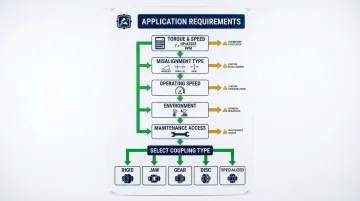
How to Select the Right Shaft Coupling for Your Application
Proper coupling selection starts with understanding your specific application requirements rather than choosing based on price or availability alone.
Identify torque requirements: Calculate the maximum torque the coupling must transmit using the formula: Torque (in-lbs) = (HP × 63,025) / RPM. Include safety factors for shock loads—API 671 recommends a minimum service factor of 1.5 for general rotating equipment to account for off-design conditions.
While AGMA 922-A96 provides service factors for initial selection, relying solely on them can lead to oversized couplings.
Assess misalignment type and magnitude: Measure or estimate angular, parallel, and axial misalignment present in the system. Different coupling types handle different misalignment combinations:
- Angular misalignment: ISO 10441 specifies minimum 0.2° per flexible element
- Equipment limits are often tighter than coupling capabilities
- Couplings should accommodate misalignment, not define allowable limits
Evaluate operating speed: Check maximum operating speed against manufacturer ratings. High-speed applications require special consideration.
Component balancing with assembly check balance minimizes residual unbalance and vibration. API 671 mandates rigorous balancing methods for high-speed applications—disc and diaphragm couplings are preferred due to their balance retention.
Consider environmental factors: Identify temperature extremes, chemical exposure, moisture conditions, and contamination risks.
Material selection varies by environment:
- Elastomeric elements: Sensitive to chemicals and heat (NBR operates -40°F to 212°F; Hytrel operates -60°F to 250°F)
- Stainless steel disc packs: High resistance to harsh conditions
- Outdoor applications: UV light, moisture, and temperature cycling require specialized materials
Assess maintenance access and requirements: Determine whether the coupling can be serviced in place and evaluate lubrication frequency needs.
Maintenance requirements vary by type:
- Gear and grid couplings: Require periodic lubrication
- Disc, diaphragm, and elastomeric couplings: Maintenance-free operation
- Metallic couplings: Higher initial cost but no lubrication needed, potentially outlasting connected equipment
Factor maintenance downtime costs into your selection decision.
Special considerations for heavy machinery: Equipment operating outdoors faces temperature extremes, moisture, debris, and UV exposure. Select couplings with appropriate material resistance and fail-safe characteristics.
Robust couplings that handle shock loads and environmental exposure are essential for reliable long-term operation in demanding applications.
Common Mistakes to Avoid When Choosing Shaft Couplings
Avoid these common selection errors that lead to premature failure and costly downtime:
Prioritizing initial cost over total ownership cost — Cheap couplings require frequent replacement and cause more downtime. Finite-life types (gear, grid) have lower upfront costs but need periodic maintenance, while infinite-life designs (disc, diaphragm) cost more initially but require minimal ongoing expenses.
Assuming perfect shaft alignment — Shafts are rarely perfectly aligned in real-world conditions. Excessive misalignment promotes rapid tooth wear in gear couplings and creates high bending stresses in disc couplings, leading to fatigue cracks near bolt holes. Misalignment is a leading cause of bearing and seal failures, vibration, and broken shafts.
Ignoring environmental conditions — Materials and lubricants must match operating temperatures, chemicals, and moisture levels. Elastomeric elements fail when exposed to high temperatures, UV light, or chemical contamination. Selecting lubrication-dependent couplings for hard-to-access locations creates maintenance headaches and reliability issues.
Conclusion
Selecting the right shaft coupling requires matching mechanical characteristics to your specific operating conditions. Each coupling type offers distinct advantages for connecting shafts, transmitting torque, and protecting equipment from damaging forces.
Multiple coupling types exist because industrial applications have vastly different demands. Critical factors that drive coupling selection include:
- Torque capacity and speed requirements
- Misalignment tolerance (angular, parallel, axial)
- Operating environment (temperature, contamination, vibration)
- Maintenance access and service intervals
- Installation space constraints
Matching coupling characteristics to your machinery needs directly impacts equipment reliability and maintenance costs. Whether you're maintaining firewood processing equipment, agricultural machinery, or construction equipment, the right coupling protects your investment and extends component lifespan.
For power transmission components including couplers, sprockets, and bellhousings for heavy machinery applications, HydraWolf Hydraulics offers American-made replacement parts backed by direct technical support from experienced machinery operators.
Frequently Asked Questions
What is a shaft coupling used for?
Shaft couplings connect two rotating shafts to transmit power while accommodating misalignment and absorbing shock. They protect connected equipment from vibration and load variations, preventing bearing failure and extending equipment life.
What are the three types of couplers?
The three main categories are rigid couplings (no flexibility, precise alignment required), flexible couplings (accommodate misalignment and dampen vibration), and fluid couplings (hydraulic power transmission with overload protection).
How does alignment affect a gear coupling?
Gear couplings handle moderate angular misalignment (1.5° per mesh) through crowned tooth design, but excessive misalignment accelerates wear. This increases vibration, requires more frequent lubrication, and causes premature failure.
Is Oldham coupling used to connect two shafts?
Yes, Oldham couplings connect two parallel shafts with lateral (parallel) offset, using a three-disc design where the center disc slides in perpendicular grooves to accommodate misalignment up to 10% of the coupling's outer diameter.
What is the difference between rigid and flexible couplings?
Rigid couplings require precise alignment and transmit torque as a solid unit with no flexibility. Flexible couplings accommodate misalignment and dampen vibration, making them suitable for most applications where perfect alignment cannot be maintained.
When should you use a flexible coupling instead of a rigid coupling?
Use flexible couplings whenever misalignment exists or may develop, when vibration dampening is needed, when thermal expansion occurs, or when shock loads are present. This covers most industrial applications where perfect alignment is difficult to maintain.