Introduction
When a shaft coupling fails in heavy equipment, the financial consequences hit immediately. Organizations face over $100,000 in losses per hour of unplanned downtime [SOURCE_NEEDED], with heavy equipment operators averaging $740 per hour in lost productivity, overtime, and delays.
For firewood processing operations, construction sites, and agricultural facilities, these failures don't just stop production—they lead to missed deliveries, safety incidents, and emergency repair costs.
Most coupling failures are preventable. Improper selection causes:
- Premature wear from misalignment
- Catastrophic breakage from inadequate torque capacity
- Excessive vibration that damages motors and gearboxes
In demanding applications—where equipment endures shock loads, frame flex, temperature extremes, and continuous duty cycles—choosing the right coupling protects your operation and your bottom line.
Key Takeaways
- Calculate design torque with appropriate service factors: 1.5-2.0 for processors, 2.0-2.5 for hydraulic equipment, 2.5-3.0 for crushers
- Match coupling type to demands: jaw for vibration dampening, gear for high torque, disc for precision alignment
- Verify misalignment tolerance—flexible couplings handle angular, parallel, and axial shifts that rigid types cannot
- Partner with experienced suppliers to address shock loads, outdoor conditions, and maintenance access requirements
What Are Shaft Couplings for Heavy Equipment?
Shaft couplings are mechanical devices that connect two rotating shafts to transmit power and torque from a driver (motor, engine, hydraulic motor) to driven equipment such as pumps, conveyors, splitters, and processing machinery. In heavy equipment contexts, these components face far more demanding conditions than general industrial applications.
Heavy equipment couplings must handle high torque loads measured in tens of thousands of inch-pounds, absorb sudden shock loads from material impacts or hydraulic surges, and accommodate misalignment caused by frame flex, thermal expansion, and foundation settling.
They operate in harsh environmental conditions including temperature swings from -20°F to 250°F, exposure to moisture and dust, and the constant vibration inherent to mobile and outdoor equipment.
Core Functions of Shaft Couplings
Transmit rotational power from driver to driven equipment with maximum efficiency and minimum energy loss. In a firewood processor, this means transferring engine power through the drivetrain to the hydraulic pump. In a conveyor system, it connects the motor to the drive roller.
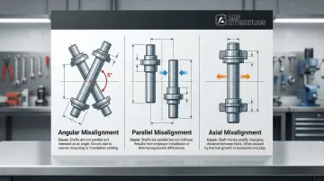
Misalignment accommodation is equally critical. Heavy equipment experiences three types of misalignment simultaneously:
- Angular misalignment occurs when shaft centerlines intersect at an angle, common in equipment with frame flex
- Parallel misalignment happens when shafts are offset but remain parallel, caused by foundation settling or mounting variations
- Axial misalignment involves shaft movement along the axis due to thermal expansion or bearing wear
Rigid couplings tolerate zero misalignment, while elastomeric tire couplings can accommodate up to 4° angular and 0.125 inches parallel offset. Operating beyond these limits transfers destructive reaction forces to bearings and seals, cutting service life dramatically.
Vibration dampening and shock absorption protect expensive components from peak loads. Elastomeric elements in jaw couplings compress under sudden torque spikes, spreading impact energy over time rather than transmitting it instantaneously to the motor or gearbox. This cushioning effect is essential in applications like log splitters where hydraulic cylinders create sudden load reversals.
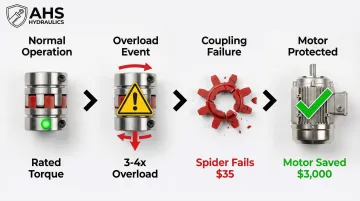
Beyond operational benefits, couplings provide a practical disconnect point for maintenance and can serve as a designed failure point. Many jaw couplings are engineered to fail at 3-4 times rated torque, sacrificing a $35 elastomer spider to protect a $3,000 motor from overload damage.
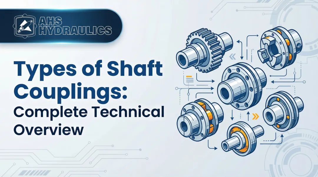
Main Types of Shaft Couplings for Heavy Equipment
Coupling types fall into two main categories—rigid and flexible—each suited for different heavy equipment applications based on alignment precision, torque requirements, and operating conditions.
Rigid Couplings
Rigid couplings (sleeve, flanged, clamp-style) provide solid connections with zero flexibility. They're ideal for applications requiring precise shaft alignment and maximum torque transmission, with models capable of handling over 1,300,000 in-lbs of torque.
These couplings work best for well-aligned, rigidly supported shafts where misalignment is minimal and torsional stiffness is critical. Because they cannot absorb any misalignment, they transfer all stresses directly to shafts and bearings.
This makes them unsuitable for mobile equipment or applications with thermal expansion, but excellent for precision machinery with carefully aligned, supported shafts.
Flexible Couplings
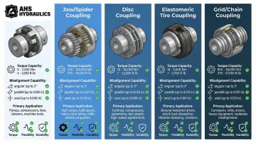
Jaw (spider) couplings are economical options handling moderate misalignment through elastomer inserts. Available in sizes from 3.5 in-lbs to 170,000 in-lbs torque capacity, they're commonly used in general industrial and agricultural applications.
Elastomer material selection dramatically affects performance:
- NBR (Buna-N): Standard, oil-resistant, -40°F to 212°F
- Urethane: 1.5x torque capacity of NBR, -30°F to 160°F
- Hytrel: 2.5x torque capacity of NBR, -60°F to 250°F for extreme conditions
Gear couplings are heavy-duty options capable of transmitting extremely high torque—up to 47,269,000 in-lbs—while handling angular misalignment of approximately 1.5° per gear mesh. Construction and mining equipment, steel mills, and heavy conveyors commonly use them.
The tradeoff is maintenance: gear couplings require periodic lubrication and seal integrity to prevent wear.
Disc couplings offer high-performance characteristics including zero backlash, high torsional stiffness, and excellent misalignment capacity without wearing parts. They provide theoretically infinite life if properly sized and aligned within limits, making them suitable for precision applications and high-speed equipment.
Single disc packs handle angular offset only; double disc designs with spacers handle angular, parallel, and axial misalignment simultaneously.
For mobile equipment and harsh conditions, elastomeric tire/sleeve couplings excel at shock absorption and vibration isolation. With superior misalignment capability (up to 4° angular, 0.125" parallel), they're ideal for equipment subject to frame flex and outdoor temperature extremes.
Grid and chain couplings offer unique benefits for specific applications. Grid couplings combine high torque capacity with moderate vibration damping, reducing vibration levels by up to 30% while requiring only periodic lubrication. Chain couplings are rugged and economical, particularly suitable for agricultural equipment, handling up to 2° angular misalignment with straightforward maintenance.
Key Selection Criteria for Heavy Equipment Couplings
Proper coupling selection requires evaluating multiple factors simultaneously to ensure the coupling matches both mechanical requirements and operating environment.
Selecting based on a single parameter—typically the lowest price for a given bore size—is the most common path to premature failure.
Torque Capacity and Service Factors
Start by determining required torque capacity. The rated motor torque is only the beginning—you must account for peak loads, shock factors, and duty cycle specific to your equipment type.
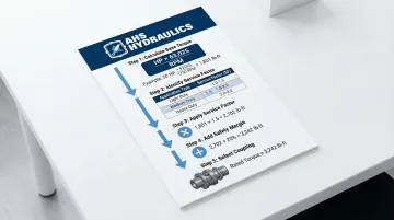
Calculate design torque using this formula:
Design Torque (in-lb) = (HP × 63,025 / RPM) × Service Factor
Or in metric units:
Design Torque (Nm) = (kW × 9,550 / RPM) × Service Factor
Service factors account for application characteristics:
- Uniform loads (1.0-1.5): Centrifugal pumps, blowers, steady conveyors
- Moderate shock (1.5-2.0): Firewood processors, screw conveyors, agitators, rotary pumps
- Heavy shock with reversing loads (2.0-3.0): Hydraulic applications, crushers, reciprocating compressors, rolling mills
For internal combustion engines with 4+ cylinders driving the equipment, add 0.5 to the service factor to account for engine torque pulses.
Select a coupling with rated torque 20-30% above your calculated design torque. This safety margin accounts for unexpected overloads, equipment wear, and variations in operating conditions.
Misalignment Tolerance
Heavy equipment experiences all three misalignment types simultaneously due to thermal expansion, foundation settling, and frame flex.
A firewood processor operating outdoors may see 40°F temperature swings during a single shift, causing significant shaft expansion. Mobile equipment on uneven terrain constantly experiences angular misalignment as the frame flexes.
Assess your application's misalignment conditions:
- Measure or estimate angular offset between shafts (typically 0.5-2° in heavy equipment)
- Calculate parallel offset in inches or millimeters
- Determine axial float requirements from thermal expansion