Introduction
A hydraulic system failure on heavy machinery often traces back to a single connection point—the female JIC fitting. Whether you're maintaining a firewood processor, log splitter, or construction equipment, that small threaded port can mean the difference between smooth operation and hours of costly downtime.
Female JIC fittings serve as the primary connection point on hydraulic cylinders, pumps, valves, and manifolds. While JIC (Joint Industry Council) fittings are industry-standard across North America, understanding the female connection specifically is crucial for system assembly, maintenance, and troubleshooting.
The 37-degree flared seat design creates a metal-to-metal seal that handles high pressure without O-rings—but only when correctly identified and installed.
What follows covers identification methods, technical specifications, installation best practices, and real-world applications—everything you need to select, install, and maintain female JIC connections with confidence.
TLDR: Key Takeaways
- 37-degree metal-to-metal seal eliminates need for O-rings or thread sealants
- Identify by UN/UNF threads, 37-degree internal flare, and dash size markings
- Straight, elbow, tee, swivel, and bulkhead styles accommodate different routing needs
- Proper torque specs prevent thread damage and leaks during installation
- Pressure ratings: -4 size handles ~5,000 PSI, -24 size handles ~2,000 PSI
What is a Female JIC Fitting?
A female JIC fitting is a hydraulic connector conforming to SAE J514 and ISO 8434-2 standards, featuring internal threads and a 37-degree internal flared seating surface. This precision-engineered component receives the male JIC fitting's nose to create a reliable, high-pressure seal.
The Three-Component Assembly System
A complete JIC connection consists of three distinct parts:
- Female fitting body - Contains internal threads and 37-degree flare cone
- Male fitting/tube - Features external threads and 37-degree nose
- Sleeve and nut - Distributes clamping force and prevents tube twist during assembly
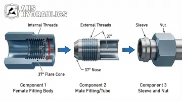
The threads provide mechanical holding power, but the seal occurs at the flare interface—not at the threads themselves.
Metal-to-Metal Sealing Principle
When properly assembled, the male fitting's 37-degree nose compresses against the female's internal flare cone. This metal-to-metal contact creates a leak-resistant seal capable of withstanding pressures up to 10,000 PSI (depending on size and material) without requiring O-rings or thread sealants.
According to the International Fluid Power Society, approximately 38% of hydraulic leaks result from incorrect assembly practices like over-tightening or misalignment—so proper understanding of female JIC connections is essential.
Female vs. Male JIC Fittings
Female fittings have internal threads and receive the male component, while male fittings have external threads and a protruding flared nose. Functionally, female fittings typically serve as port connections on equipment, manifolds, or adapters, whereas male fittings usually terminate hoses or tubes for connection to female ports.
Swivel advantage: Female swivel fittings allow orientation adjustment during installation without twisting the connected hose, reducing stress and simplifying assembly in confined spaces.
Why Female JIC Connections Matter
Female ports are standard on hydraulic cylinders, pumps, valves, and manifolds—making them the primary connection point for system assembly. Proper female fitting selection directly affects:
- Flow characteristics - Internal geometry impacts fluid velocity and turbulence
- Pressure ratings - Size and material determine maximum working pressure
- Leak prevention - Flare seat condition and proper torque ensure seal integrity
- System reliability - Quality fittings withstand vibration, thermal cycling, and contamination
In heavy machinery applications, female fittings must maintain seal integrity despite harsh operating conditions—a critical requirement for equipment like firewood processors and construction machinery. HydraWolf Hydraulics manufactures female JIC fittings designed specifically for these demanding environments, drawing on over a decade of experience in firewood processing and heavy equipment applications where reliability is non-negotiable.
How to Identify Female JIC Fittings
Visual Identification Characteristics
Look for these distinctive features:
- 37-degree internal flare cone — visible when examining the fitting opening
- Parallel straight threads (unlike tapered NPT fittings)
- Hex body shape for wrench engagement
- No O-ring grooves on the sealing face
Distinguishing from similar fittings:
- SAE 45-degree fittings have a steeper internal angle
- NPT fittings feature tapered threads that change diameter
- ORFS fittings include O-ring grooves on the sealing face
Measuring Thread Size and Pitch
Step-by-step identification:
- Use a thread pitch gauge to confirm UN or UNF thread series
- Measure the major diameter with calipers
- Match measurements to standard dash size charts
- Verify the dash size corresponds to tube OD in 1/16" increments
Common thread specifications:
| Dash Size | Tube OD | Thread Size | Female Thread I.D. |
|---|---|---|---|
| -04 | 1/4" | 7/16"-20 | 0.39" |
| -06 | 3/8" | 9/16"-18 | 0.51" |
| -08 | 1/2" | 3/4"-16 | 0.69" |
| -10 | 5/8" | 7/8"-14 | 0.81" |
| -12 | 3/4" | 1 1/16"-12 | 0.98" |
| -16 | 1" | 1 5/16"-12 | 1.23" |
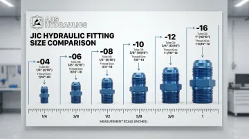
The dash number roughly corresponds to tube OD in sixteenths (dash 6 = 6/16" or 3/8" tube).
Verifying the 37-Degree Flare Angle
Use a 37-degree flare angle gauge to verify the internal cone angle. This step is critical for three reasons:
- Mating a 37-degree male with a 45-degree female port causes leaks or fitting damage
- The sealing surfaces won't properly contact if angles don't match
- Visual inspection alone cannot reliably distinguish 37-degree from 45-degree angles
Some specialized couplings feature dual-angle seats machined to accept both 37° and 45° fittings, but these are exceptions.
Reading Markings and Documentation
Female JIC fittings may include:
- Dash size numbers stamped on the hex body
- Material codes (e.g., "SS" for stainless steel)
- Pressure ratings or manufacturer logos
SAE J514 compliant fittings meet specific dimensional tolerances (37° ± 0.5° flare angle, Class 2B internal threads), though markings may be minimal on smaller sizes.
When identification is uncertain—especially for critical system components—consult manufacturer datasheets.
HydraWolf Hydraulics manufactures American-made JIC fittings with consistent quality control through in-house fabrication, ensuring components meet exact specifications.
Beyond identifying individual fittings by their markings, understanding how JIC compares to similar standards prevents costly compatibility mistakes.
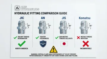
Distinguishing JIC from AN, JIS, and Komatsu Fittings
JIC vs. AN (Army-Navy):
- Dimensionally identical (both use 37-degree flare)
- AN fittings manufactured to tighter military tolerances (Class 3 threads vs. Class 2)
- Not considered interchangeable in critical or high-vibration applications despite similar appearance
JIC vs. JIS (Japanese Industrial Standard):
- JIS fittings use 30-degree flare angles
- Feature BSP or metric threads (not UN/UNF)
- Completely incompatible with JIC despite similar appearance
JIC vs. Komatsu:
- Komatsu fittings use 30-degree flare angles
- Feature metric threads
- Cannot be substituted for JIC connections
Practical advice: When working on imported equipment, verify fitting standards before ordering replacements to avoid costly mismatches.
Common Identification Mistakes to Avoid
Thread compatibility assumptions: SAE 45° fittings share thread sizes with JIC on some dash sizes (like -04, -05, -08) but have incompatible flare angles. Thread fit doesn't guarantee seal compatibility.
Over-tightening during testing: Forcing connections to check compatibility damages flare seats, compromising future seal integrity even with correct fittings.
Mixing JIC and AN fittings: While dimensionally similar, tolerance differences can cause issues in high-vibration applications. Understand the implications before mixing standards in the same system.
Technical Specifications and Standards
SAE J514 Standard Requirements
SAE J514 defines comprehensive specifications for JIC fittings:
- Dimensional tolerances for flare seats and thread specifications
- Flare angle requirement: 37° ± 0.5°
- Thread class: Class 2B for female internal threads
- Material requirements and pressure rating guidelines
This standard replaced the older MS16142 military specification, though some tooling and documentation still references the MS number.
Understanding these standards helps explain why material selection plays such a critical role in fitting performance.
Material Options and Selection
Each material offers distinct advantages depending on your application requirements:
Carbon steel provides the most economical option for general industrial applications. It requires plating for corrosion resistance and handles temperatures from -20°F to +400°F.
Stainless steel 316 delivers superior corrosion resistance for harsh environments like marine, chemical, and outdoor applications. While higher in cost, it offers longer service life and temperature tolerance from -60°F to +400°F or higher.
Brass works well for low-pressure, non-critical applications but has limited pressure ratings (typically 1,000-2,000 PSI) and a narrower temperature range of -40°F to +175°F. It's not recommended for heavy machinery hydraulics.
When selecting material, consider these factors:
- Operating pressure and temperature range
- Fluid compatibility (hydraulic oil, water-glycol, etc.)
- Environmental exposure (moisture, chemicals, salt spray)
- Vibration levels and cycle frequency
For applications requiring reliable American-made components, HydraWolf Hydraulics manufactures JIC fittings using North American-sourced materials with in-house fabrication for superior quality control.
Pressure and Temperature Ratings
Pressure ratings by size and material:
| Dash Size | Carbon Steel | Stainless Steel | Brass |
|---|---|---|---|
| -04 (1/4 in) | 5,000 PSI | 5,000 PSI | 2,000 PSI |
| -06 (3/8 in) | 5,000 PSI | 4,000 PSI | 1,200 PSI |
| -08 (1/2 in) | 4,500 PSI | 4,000 PSI | 1,200 PSI |
| -12 (3/4 in) | 3,500 PSI | 3,000 PSI | 1,200 PSI |
| -16 (1 in) | 3,000 PSI | 2,500 PSI | 1,000 PSI |
| -24 (1-1/2 in) | 2,000 PSI | 1,500 PSI | 1,000 PSI |
These ratings assume proper installation and maintenance. Keep these factors in mind:
- Working pressure should be significantly lower than burst pressure (typically 4:1 safety factor)
- Pressure ratings decrease as fitting size increases
- Temperature increase reduces pressure ratings
- Vibration can reduce effective working pressure
- Always consult manufacturer specifications for critical applications
The metal-to-metal seal design makes JIC fittings suitable for high-temperature applications where O-rings would fail (up to 400°F+ depending on material).
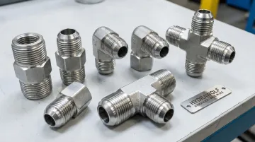
Female JIC Fitting Types and Configurations
Straight Female JIC Fittings
Inline configuration for direct hose-to-equipment connections without directional changes.
Common applications:
- Hydraulic cylinder port connections where direct alignment minimizes fitting count
- Pump inlet and outlet ports requiring unrestricted flow paths
- Manifold connections where straight alignment optimizes space utilization
- Direct tube-to-equipment interfaces in accessible mounting locations
Bulkhead variations allow panel mounting with female JIC connections on one or both sides, creating accessible connection points through equipment frames or enclosures.
Elbow Female JIC Fittings
Available in two primary angles:
- 45-degree elbows for moderate directional changes in gradual routing applications
- 90-degree elbows for right-angle flow redirection in tight quarters
When to use elbows:
- Tight spaces where straight fittings create excessive hose bending stress
- Routing around obstacles or structural components
- Reducing hose twist and improving service life
- Achieving optimal hose orientation in confined areas
Adjustable options: Swivel female elbows allow precise hose orientation after installation, facilitating alignment without disconnecting the fitting.
Tee and Cross Female JIC Fittings
Available in two branch configurations:
- Female tees provide three connection points for system branching and auxiliary circuits
- Crosses offer four connection points for complex routing in multi-directional systems
Typical applications:
- Creating auxiliary ports for pressure gauges or test equipment
- Adding branch circuits to existing lines
- Connecting multiple actuators to a single supply line
- Establishing pressure monitoring or sampling points
The through-flow path (run) typically has less flow restriction than the perpendicular branch port—important for minimizing pressure drop in primary circuits.
Swivel Female JIC Fittings
Design features:
- Rotating female body allows 360-degree hose orientation adjustment without disconnecting lines
- Captured O-ring or backup ring maintains seal integrity during rotation and under pressure
- Independent swivel movement between rotating body and fixed connection point
Key advantages:
- Simplifies installation in confined spaces by allowing final orientation after initial connection
- Reduces hose twist and associated mechanical stress that shortens hose service life
- Enables optimal routing to be achieved after system pressurization and testing
- Facilitates maintenance by allowing hose repositioning during reassembly
For challenging installations requiring branch connections with rotational adjustment, swivel run tee fittings like HydraWolf's F5706X16X16X16 (#16 Swivel Nut Run Tee) feature 1" JIC Female Swivel capability with full 360-degree rotation.
Specialty Female JIC Configurations
Reducer fittings:
- Female JIC on one end with smaller or larger connection on the other
- Allows connection between different dash sizes
- Available in JIC-to-JIC, JIC-to-NPT, and other combinations
Union fittings:
- Allow disconnection of rigid tube runs without disturbing connected equipment
- Facilitate maintenance and system reconfiguration
Adapter fittings:
- Convert female JIC to NPT, ORFS, BSP, or other thread standards
- Enable system integration across different fitting types
- Essential for connecting equipment with mixed standards
Installation and Assembly Guide for Female JIC Fittings
Pre-Installation Inspection
Check female fitting threads:
- Inspect for damage, cross-threading, or debris
- Use a thread chaser to clean threads without removing material
- Verify thread class matches male fitting (Class 2B female with Class 2A male)
Inspect internal flare seat:
- Look for nicks, scratches, or deformation
- Even minor imperfections prevent proper sealing
- Replace fittings with damaged flare seats (don't attempt to repair)
Verify mating components:
- Confirm male fitting has clean, undamaged flare
- Match thread sizes between male and female components
- Ensure all parts are free of contamination
Proper Assembly Technique
The "No Sealant" Rule: JIC fittings should NEVER use thread sealant or PTFE tape. The seal occurs at the 37-degree flare interface, not the threads.
Sealants interfere with proper seating and introduce contaminants into hydraulic systems.
Assembly Procedure
Follow these steps for leak-free connections:
- Hand-thread the male fitting into the female fitting until resistance is felt (ensures proper engagement without cross-threading)
- Apply appropriate torque using the FFWR (Flats From Wrench Resistance) method (see table below)
- Position swivel fittings in desired orientation before final tightening
- Avoid excessive force (over-torquing damages threads or flares)
Installation specifications (FFWR method):
| Dash Size | Thread Size | Assembly Torque | Tube Connection | Swivel Nut/Hose |
|---|---|---|---|---|
| -04 | 7/16"-20 | 11-13 ft-lb | 2 Flats | 2 Flats |
| -06 | 9/16"-18 | 20-22 ft-lb | 2 Flats | 1.5 Flats |
| -08 | 3/4"-16 | 43-47 ft-lb | 1.5 Flats | 1 Flat |
| -10 | 7/8"-14 | 55-65 ft-lb | 1.5 Flats | 1 Flat |
| -12 | 1 1/16"-12 | 80-90 ft-lb | 1.25 Flats | 1 Flat |
| -16 | 1 5/16"-12 | 115-125 ft-lb | 1 Flat | 1 Flat |
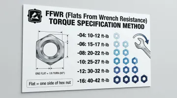
Note: "Flat" refers to one side of the hex nut (1/6 turn). The FFWR method accounts for variables like plating and lubrication that affect torque readings.
Post-Installation Testing
Once assembly is complete, verify connection integrity through pressure testing.
Pressure test procedure:
- Gradually pressurize the system while monitoring connections
- Watch for weeping or seepage at female JIC connections
- Minor leakage may resolve with additional tightening (1/6 to 1/3 turn)
- If leaks persist, disassemble and inspect rather than forcing
Follow-up inspection:
- Re-inspect connections after first operating cycle
- Check after system experiences full pressure and temperature ranges
- Document torque values for critical connections
- Establish baseline maintenance data for future reference
Troubleshooting Installation Issues
Thread binding during assembly:
- Stop immediately (forcing damages threads)
- Check for cross-threading or debris
- Clean threads and verify proper alignment before retrying
Persistent leaks despite proper torque:
- Inspect both male and female flare surfaces for damage
- Even minor imperfections prevent sealing
- Replace damaged components rather than using excessive torque
Repeated connection failures:
- Consider whether vibration, thermal cycling, or pressure spikes exceed design limits
- Evaluate hose routing and support to minimize stress
- Verify material selection matches application requirements
Replacement fitting verification:
- Ensure replacement matches both thread size and flare angle
- Using incorrect specifications guarantees failure
- Source replacement fittings from manufacturers who provide detailed specifications and quality documentation
Common Applications in Heavy Machinery
Hydraulic Cylinders and Actuators
Female JIC ports are standard on hydraulic cylinder rod and base ends, providing connection points for hoses that supply pressurized fluid for extend/retract operations.
Why JIC suits cylinder applications:
- Reusability - Enables maintenance and cylinder replacement
- High pressure capability - Handles demanding hydraulic pressures
- Vibration resistance - Maintains seal integrity in mobile equipment
- Temperature performance - Metal-to-metal seal tolerates heat generation
Firewood processors, log splitters, and construction equipment all depend on these connections for reliable cylinder operation under demanding conditions.
Hydraulic Pumps and Motors
Beyond cylinders, female JIC ports handle the extreme conditions found at pump and motor connection points.
Common connection locations:
- Pump inlets for supply lines from the reservoir
- Pressure outlets carrying high-pressure flow to the system
- Case drains returning internal leakage to the tank
The metal-to-metal seal excels in high-temperature environments near pumps and motors. Heat generation in these areas would quickly degrade O-ring seals, but JIC connections maintain integrity.
Control Valves and Manifolds
Control systems present unique packaging challenges where female JIC connections provide distinct advantages.
You'll find female JIC ports on directional control valves (work port connections), pressure relief valves (system protection), and manifold blocks (compact integration). The female port design enables tight packaging in manifolds while simplifying hose routing in confined spaces.
Key advantages for control applications:
- Connections can be broken without replacing fittings (maintenance access)
- Reusability simplifies system modifications and troubleshooting
- Manifold-mounted female ports enable compact system designs
- Reliable sealing under repeated connect/disconnect cycles
This combination makes female JIC connections ideal for systems requiring periodic maintenance or configuration changes.
Troubleshooting and Maintenance
Common Failure Modes
Thread damage:
- Caused by cross-threading or over-torquing
- Damaged threads cannot maintain proper preload
- Results in persistent leaks regardless of tightening
- Prevention: Hand-thread until resistance, then apply proper torque
Flare seat deformation:
- Results from repeated assembly/disassembly cycles
- Contamination between sealing surfaces accelerates wear
- Once deformed, the fitting must be replaced
- Prevention: Inspect flare seats before each assembly, keep surfaces clean
Vibration-induced loosening:
- Common in mobile equipment applications
- Metal-to-metal seal can relax over time
- Mitigation: Use additional support clamps, optimize hose routing to minimize vibration transmission
According to industry data, approximately 38% of hydraulic leaks result from incorrect assembly practices. This makes proper installation technique critical for preventing failures.
Preventive Maintenance Practices
Periodic inspection:
- Check female JIC connections for signs of weeping or seepage
- Look for corrosion or mechanical damage
- Inspect during scheduled maintenance intervals
- Address minor issues before they become major failures
Spare parts inventory:
- Keep common sizes on hand for quick replacement
- Source quality components from manufacturers like HydraWolf Hydraulics
- American-made components ensure consistent quality and specifications
- Proper inventory reduces downtime during maintenance
Documentation:
- Record torque values for critical connections
- Note inspection dates and findings
- Track maintenance history to identify patterns
- Establish baseline data for future reference
Regular inspections and documentation help you identify when fittings have reached the end of their service life. Watch for these replacement indicators:
When to Replace Female JIC Fittings
Damaged threads: If a thread chaser cannot restore proper engagement, the fitting needs replacement. Compromised threads will not maintain seal integrity, and excessive torque won't compensate for the damage.
Deformed flare seats: Fittings with scored or deformed sealing surfaces must be replaced. Excessive torque worsens the damage rather than improving the seal. Visual inspection may not reveal minor deformation—test fit with a new male component to verify condition.
High-cycle applications: After multiple assembly/disassembly cycles, consider preventive replacement. Repeated use can work-harden and eventually crack the flare, particularly in high-pressure applications. The cost of a new fitting is far less than system failure and downtime.
Frequently Asked Questions
What is a female JIC fitting?
A female JIC fitting features internal threads and a 37-degree flare cone seat that creates a metal-to-metal seal with male fittings, conforming to SAE J514 standards. The seal forms at the flare interface, not the threads.
How do I identify JIC fittings and determine their size?
Check for parallel UN/UNF threads (not tapered), verify the 37-degree flare angle, then measure thread diameter and pitch with calipers. Match your measurements to standard dash size charts—for example, 9/16"-18 threads indicate dash 6.
What is the nomenclature for JIC fittings?
JIC nomenclature includes dash size (tube OD in 1/16" increments), configuration type (straight, elbow, tee), and thread specification (UN/UNF size and pitch). Example: "JIC 6 Female Elbow 9/16-18" indicates a dash 6 elbow fitting with 9/16-18 threads.
Can I use JIC and AN fittings interchangeably?
Use caution—while dimensionally identical, AN fittings have tighter military tolerances (Class 3 vs. Class 2 threads). They shouldn't be considered interchangeable in critical or high-vibration applications without engineering approval.
What's the difference between 37-degree JIC and 45-degree SAE fittings?
Despite some shared thread sizes, the different flare angles make these fittings incompatible. The 37-degree and 45-degree sealing surfaces won't properly contact, resulting in leaks or fitting damage if you attempt to mate them.
Do female JIC fittings require thread sealant or tape?
No—never use thread sealant or PTFE tape on JIC fittings. The seal forms through metal-to-metal contact at the 37-degree flare interface, and sealants interfere with proper seating while contaminating hydraulic systems.