Introduction
A commercial firewood processor suddenly shuts down mid-shift. Hydraulic fluid pools beneath the machine. The cause? A single mismatched JIC fitting that failed under pressure, causing a leak that forced an emergency stop.
For the operator, this means hours of downtime, costly repairs, and lost production—all because the replacement fitting was measured incorrectly.
This scenario happens more often than it should. Accurate measurement is the foundation of reliable hydraulic connections in agriculture, construction, and industrial equipment.
JIC (Joint Industry Council) fittings are the workhorse of high-pressure hydraulic systems, handling pressures up to 7,500 psi in demanding environments. Their reliability depends entirely on correct identification and sizing. One wrong measurement—confusing a -8 for a -6, or mistaking a 37-degree flare for a 45-degree SAE fitting—compromises your entire hydraulic system.
This guide shows you how to measure JIC fittings correctly, identify them with confidence, and avoid costly mistakes.
Key Takeaways
- JIC fittings use straight threads with a 37-degree metal-to-metal flare seal, standardized under SAE J514
- Three critical measurements: thread outer diameter (OD), threads per inch (TPI), and 37-degree flare angle verification
- Essential tools: digital calipers (0.01" accuracy), thread pitch gauge, and angle gauge
- Dash size corresponds to tube OD in sixteenths (e.g., -8 = 8/16" = 1/2" tube)
- Cross-reference measurements with SAE J514 charts to confirm size
Understanding JIC Fitting Basics
What Are JIC Fittings?
JIC (Joint Industry Council) fittings are compression-type hydraulic connectors defined by the SAE J514 standard. Originally developed in the 1950s to standardize hydraulic connections across industrial equipment, JIC fittings became the industry standard for high-pressure, high-vibration applications.
Today, they're found in everything from firewood processors and log splitters to construction equipment and agricultural machinery.
The 37-Degree Flare Design
The defining feature of a JIC fitting is its 37-degree flare angle. Unlike pipe fittings that rely on thread interference or O-rings, JIC fittings create a metal-to-metal seal through line contact between the male cone and the flared tube or female cone seat. This design delivers several advantages:
- No thread sealant required - The seal forms at the flare, not the threads
- High pressure capacity - Handles up to 7,500 psi in dynamic applications
- Vibration resistance - Metal-to-metal contact maintains seal integrity under constant movement
- Reusability - Can be connected and reconnected multiple times without degradation
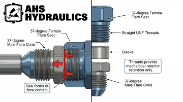
The straight threads (UNF series) serve a purely mechanical function—holding the connection together to maintain the seal. They don't provide sealing themselves.
Common Applications in Heavy Machinery
These design advantages explain why JIC fittings dominate high-pressure hydraulic systems in industries where reliability is critical:
Firewood Processing Equipment: Commercial log splitters and firewood processors use JIC fittings throughout their hydraulic circuits. These machines require heavy-duty connections to handle the extreme forces involved in splitting full pole logs, controlling wedge lifts, and operating conveyor systems.
Construction Equipment: Forklifts, bulldozers, and excavators rely on JIC fittings for hydraulic cylinders that power booms, buckets, and blade controls. The fittings withstand constant vibration, shock loads, and exposure to harsh environmental conditions.
Agricultural Machinery: Tractors, combines, and harvesters use JIC connections for loader bucket controls, implement height adjustments, and three-point hitch systems. The fittings must perform reliably through seasonal temperature extremes and dusty field conditions.
Marine Applications: Hydraulic steering systems, winches, and stabilizers in boats and ships use JIC fittings for their corrosion resistance and ability to maintain seals in high-vibration environments.
These applications share three requirements: proven pressure handling, field serviceability, and compatibility with standard hydraulic components across manufacturers.
What You Need to Measure JIC Fittings
Having the right measurement tools prevents costly misidentification and ordering errors. A visual guess isn't enough—JIC fittings look nearly identical to SAE 45-degree fittings, and the difference is only detectable through precise measurement.
Essential Measurement Tools
Digital or Dial Calipers (Minimum 6-Inch Capacity): Calipers measure thread outer diameter with 0.01mm (0.0004") accuracy. A standard ruler lacks the precision needed—you need accuracy to within 0.01 inches for reliable identification.
Digital calipers are easier to read, but dial calipers work equally well if properly maintained.
Thread Pitch Gauge (Inch-Based): A thread pitch gauge determines threads per inch (TPI). The gauge consists of multiple blades, each stamped with a specific TPI value. You press different blades against the threads until one matches perfectly with no gaps between the gauge teeth and the thread pattern. This confirms the exact pitch.
Angle Gauge or Protractor: An angle gauge verifies the 37-degree flare angle that distinguishes JIC from other fitting types. If the centerline of the fitting and the gauge are parallel when the gauge is placed against the flare surface, the angles match. This single check prevents the most common identification error—confusing JIC (37°) with SAE automotive fittings (45°).
Clean Cloth and Wire Brush: Dirt, grease, and corrosion interfere with accurate measurements. A wire brush removes stubborn buildup from threads, while a clean cloth wipes away residual contamination. Clean measurement surfaces are essential to avoid false readings that lead to wrong part orders.
Preparation and Safety Precautions
Depressurize and Isolate the System: Before removing any fitting for measurement, ensure the hydraulic system is completely depressurized. Shutting off the pump isn't sufficient—accumulators or closed valves can trap pressure in specific circuit sections.
Check pressure gauges to verify they read zero, and open bleed valves to exhaust trapped fluid.
OSHA standard 1910.147 requires lockout/tagout procedures for hydraulic systems. This means disconnecting power sources, relieving stored energy, and using locks or tags to prevent accidental re-energization.
Trapped hydraulic pressure poses severe injection injury risks—fluid under pressure can penetrate skin and cause serious tissue damage.
Clean the Fitting Thoroughly: Once removed, clean the fitting completely. Focus on threads and the flare surface, as these are your measurement points. Remove all hydraulic fluid, dirt, and corrosion. If threads appear damaged or excessively worn during cleaning, consider replacing the fitting rather than attempting to measure and reuse it.
Step-by-Step Methods to Measure JIC Fittings
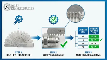
Accurate JIC fitting identification requires three critical measurements performed in sequence. All three must match standard specifications to confirm the fitting type and size.
Method 1: Measuring Thread Diameter
This measurement determines the nominal dash size designation of the JIC fitting (e.g., -4, -6, -8, -12, -16).
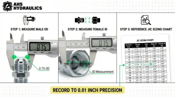
Step 1: Position Your Calipers For male fittings, measure the outer diameter (OD) of the threads at the widest point—crest to crest across the threads. For female fittings, measure the inner diameter (ID) of the threaded section at the narrowest point.
Ensure the caliper jaws are perpendicular to the fitting axis for an accurate reading.
Step 2: Record in Inches JIC fittings use inch-based sizing, not metric. Record your measurement to two decimal places (e.g., 0.56" or 0.75"). If your calipers display millimeters, convert to inches by dividing by 25.4.
Step 3: Cross-Reference with Sizing Chart Compare your diameter measurement to a JIC sizing chart:
- 0.44" OD = -4 JIC fitting (7/16"-20 thread)
- 0.56" OD = -6 JIC fitting (9/16"-18 thread)
- 0.75" OD = -8 JIC fitting (3/4"-16 thread)
- 1.06" OD = -12 JIC fitting (1 1/16"-12 thread)
Important Note: Male and female fittings of the same dash size have different measured diameters. A -8 male fitting measures approximately 0.75" OD, while a -8 female fitting measures approximately 0.69" ID.
Both receive the -8 designation because they mate with 1/2" tube.
Method 2: Counting Threads Per Inch (TPI)
Once you've identified the diameter, confirming the thread pitch ensures proper engagement and sealing.
Step 1: Use the Thread Pitch Gauge Press different gauge blades against the threads until you find one that fits perfectly with no gaps. The blade teeth should nest completely into the thread valleys.
If you see light between the gauge and threads, try a different blade.
Step 2: Read the TPI Number Once you find the matching blade, read the TPI number stamped on it. Common JIC TPI values:
- 20 TPI (dash sizes -4, -5)
- 18 TPI (dash size -6)
- 16 TPI (dash size -8)
- 14 TPI (dash size -10)
- 12 TPI (dash sizes -12, -14, -16, -20, -24, -32)
Step 3: Verify the Combination Cross-reference the diameter and TPI combination against the SAE J514 standard. For example, a measurement of 9/16" diameter with 18 TPI confirms a -6 JIC fitting.
If the diameter matches but the TPI doesn't, you may have a damaged fitting or a non-JIC fitting type.
Incorrect TPI identification is a leading cause of cross-threading and damaged fittings. Even if threads appear to engage initially, a TPI mismatch will prevent proper tightening and compromise the seal.
Method 3: Verifying the 37-Degree Flare Angle
The final step confirms the fitting is JIC (37°) and not SAE 45°, NPT (tapered), or another type.
Step 1: Visual Inspection Examine the cone-shaped flare at the end of the fitting. JIC fittings have a distinct metal flare surface—smooth, machined, and free of O-ring grooves. The flare should appear relatively flat compared to sharper cone angles.
Step 2: Use an Angle Gauge Place a 37-degree angle gauge or reference tool against the flare surface. The gauge should sit flush with no gaps. The centerline of the fitting should remain parallel to the gauge centerline.
Step 3: Check for Metal-to-Metal Sealing Surface Verify there's no O-ring groove on the flare face. JIC fittings seal metal-to-metal without rubber seals. If you see an O-ring groove, you're looking at an ORFS (O-Ring Face Seal) fitting, not JIC.
Critical Distinction: If the flare angle doesn't match 37 degrees, or if the threads are parallel but there's an O-ring present, it's not a JIC fitting. SAE 45-degree fittings look nearly identical except for the angle, and mixing them causes leaks.
How to Interpret Your Measurements
Correct interpretation prevents ordering wrong fittings, which leads to leaks, system damage, and safety hazards.
The three measurements work together to accurately identify the fitting.
Matching Measurements to Standard Sizes
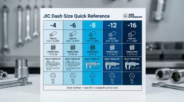
Use the three measurements—diameter, TPI, and angle—together to identify the dash size designation. The dash number relates to tube OD in sixteenths of an inch:
- -4 = 4/16" = 1/4" tube OD
- -6 = 6/16" = 3/8" tube OD
- -8 = 8/16" = 1/2" tube OD
- -12 = 12/16" = 3/4" tube OD
- -16 = 16/16" = 1" tube OD
Cross-reference your measurements with a complete SAE J514 sizing chart showing thread diameter, TPI, and hex size:
| Dash Size | Tube OD | Thread Size | Male Thread OD | TPI |
|---|---|---|---|---|
| -4 | 1/4" | 7/16"-20 | 0.44" | 20 |
| -6 | 3/8" | 9/16"-18 | 0.56" | 18 |
| -8 | 1/2" | 3/4"-16 | 0.75" | 16 |
| -12 | 3/4" | 1 1/16"-12 | 1.06" | 12 |
| -16 | 1" | 1 5/16"-12 | 1.31" | 12 |
Identifying Male vs. Female Fittings
Male fittings have external threads and a flared tube end or cone. Measure the thread OD at the crest.
Female fittings have internal threads and a flared swivel nut. Measure the thread ID and note the hex size of the nut.
Both male and female fittings of the same dash size mate correctly despite different measured diameters. A -8 male (0.75" OD) connects to a -8 female (0.69" ID)—both designed for 1/2" tube.
When Measurements Don't Match Standard Sizes
If your measurements fall between standard sizes or show unusual combinations:
- Remeasure carefully: Clean the fitting thoroughly, measure at the correct point (full thread crest, not worn sections), and verify your tools are calibrated
- Check for damage: Thread wear, cross-threading, or corrosion can alter dimensions. Inspect threads under good lighting for deformation, galling, or missing sections
- Consider non-standard fittings: Some measurements indicate obsolete, metric, or proprietary fittings that don't follow SAE J514. International equipment may use different standards entirely
- Consult a specialist: When measurements remain ambiguous after careful verification, contact a hydraulic fitting specialist. HydraWolf's technical support team has over a decade of experience identifying unusual fittings and can help determine the correct replacement for system safety and performance
Common Measurement Errors and How to Avoid Them
Measuring at the Wrong Point
The Error: Measuring thread diameter at worn or damaged sections instead of at the full thread crest gives false readings. Similarly, including the hex body in your measurement instead of just the threaded portion produces incorrect dimensions.
How to Avoid: Always measure at the widest point of external threads (crest-to-crest) or the narrowest point of internal threads. Ignore worn areas and measure where threads are fully formed and undamaged.
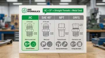
Confusing JIC with Similar Fittings
Even with accurate measurements, you can still order the wrong fitting if you misidentify the type. JIC (37° flare, straight threads) is frequently confused with:
- SAE 45° fittings (45° flare, straight threads) - used in automotive and refrigeration
- AN fittings (37° flare, straight threads) - aerospace/military standard with tighter tolerances
- NPT fittings (tapered threads) - seal on threads, not flare
- ORFS fittings (O-ring groove on flat face) - use O-ring seal, not metal-to-metal
To distinguish JIC from these lookalikes:
- JIC has straight threads + 37° metal flare
- NPT has tapered threads (measure first, fourth, and last thread—diameter changes)
- ORFS has O-ring groove on a flat face
- SAE 45° has 45° flare (sharper angle than JIC's 37°)
Use the angle gauge every time. Visual inspection alone cannot reliably distinguish 37° from 45°.
Not Accounting for Thread Wear or Damage
Worn threads, cross-threading, or corrosion make measurements inaccurate and lead to wrong size identification. Attempting to reuse damaged fittings compromises system integrity.
Inspect thread condition before measuring for these warning signs:
- Flattened or deformed thread crests
- Galling (metal transfer between mating surfaces)
- Corrosion pitting
- Missing thread sections
If you find visible damage, replace the fitting rather than measuring and attempting reuse. Damaged fittings won't seal properly even if you identify the correct size.
When to Seek Professional Help
Some fitting identification scenarios require expert knowledge and specialized equipment beyond standard measurement tools.
Seek professional assistance when:
- Measurements don't match any standard size after careful verification
- You're working with critical high-pressure applications (above 5,000 psi)
- The fitting appears to be custom, obsolete, or from international equipment
- System safety is at stake (brake systems, lifting equipment, personnel platforms)
- You suspect a metric or proprietary fitting standard
HydraWolf Hydraulics offers direct technical support from experienced designers and builders who can identify fittings and recommend correct replacements. The team handles challenging identification cases regularly from their Marathon, NY facilities.
Their professionals are also heavy machine operators and customers themselves, bringing practical field experience to technical problem-solving.
For ambiguous fittings or critical applications, expert consultation prevents costly mistakes and ensures system safety.
Frequently Asked Questions
What does JIC stand for and why is it important?
JIC stands for Joint Industry Council, which standardized these fittings in the 1950s under SAE J514. This ensures interchangeability across manufacturers—a -8 JIC fitting from any compliant manufacturer will mate correctly with any other -8 JIC fitting.
How do I know if my fitting is JIC or NPT?
JIC has straight threads with a 37-degree flare creating a metal-to-metal seal. NPT has tapered threads requiring sealant. Measure the thread diameter at three points—if it changes, it's NPT; if constant, it's likely JIC.
Can I use a regular ruler to measure JIC fittings?
No. A ruler lacks the precision needed for thread diameter measurement, which requires 0.01" accuracy. Size differences between fittings are often less than 1/4", making calipers or micrometers essential for reliable identification.
What is the significance of the 37-degree flare angle?
The 37-degree angle creates a metal-to-metal seal when tightened, providing leak-free connections in high-pressure (up to 7,500 psi) and high-vibration environments without requiring sealants. The angle provides optimal sealing surface area for reliable performance.
Do male and female JIC fittings measure the same way?
Male fittings measure external thread diameter (OD), while female fittings measure internal thread diameter (ID). However, both use the same dash size designation when they mate correctly—a -8 male and -8 female both connect to 1/2" tube despite having different measured diameters.
What should I do if my measurements fall between standard sizes?
Re-clean the fitting thoroughly, check for wear or damage that might affect measurements, and re-measure carefully at the correct points. If measurements remain ambiguous, consult a hydraulic specialist before ordering parts—incorrect fittings lead to leaks and system failure.